Skip to content

Electrical & Electronics Engineering

Electricity is oxygen of modern society.

  • Home
  • Contact
  • Power System
  • Electrical Machine
  • Special Electric Machine
  • Contact
  • Home
  • Contact
  • Power System
  • Electrical Machine
  • Special Electric Machine
  • Contact

Synchronous Motor

synchronousmotor-190815164813_page-0001synchronousmotor-190815164813_page-0002synchronousmotor-190815164813_page-0003synchronousmotor-190815164813_page-0004synchronousmotor-190815164813_page-0005synchronousmotor-190815164813_page-0006synchronousmotor-190815164813_page-0007synchronousmotor-190815164813_page-0008synchronousmotor-190815164813_page-0009synchronousmotor-190815164813_page-0010synchronousmotor-190815164813_page-0011synchronousmotor-190815164813_page-0012synchronousmotor-190815164813_page-0013synchronousmotor-190815164813_page-0014synchronousmotor-190815164813_page-0015synchronousmotor-190815164813_page-0016synchronousmotor-190815164813_page-0017synchronousmotor-190815164813_page-0018synchronousmotor-190815164813_page-0019synchronousmotor-190815164813_page-0020synchronousmotor-190815164813_page-0021synchronousmotor-190815164813_page-0022synchronousmotor-190815164813_page-0023synchronousmotor-190815164813_page-0024synchronousmotor-190815164813_page-0025synchronousmotor-190815164813_page-0026synchronousmotor-190815164813_page-0027synchronousmotor-190815164813_page-0028synchronousmotor-190815164813_page-0029synchronousmotor-190815164813_page-0030synchronousmotor-190815164813_page-0031synchronousmotor-190815164813_page-0032synchronousmotor-190815164813_page-0033synchronousmotor-190815164813_page-0034synchronousmotor-190815164813_page-0035synchronousmotor-190815164813_page-0036synchronousmotor-190815164813_page-0037synchronousmotor-190815164813_page-0038synchronousmotor-190815164813_page-0039synchronousmotor-190815164813_page-0040synchronousmotor-190815164813_page-0041synchronousmotor-190815164813_page-0042synchronousmotor-190815164813_page-0043synchronousmotor-190815164813_page-0044synchronousmotor-190815164813_page-0045synchronousmotor-190815164813_page-0046synchronousmotor-190815164813_page-0047synchronousmotor-190815164813_page-0048

Posted on March 4, 2020Categories Electrical MachineLeave a comment on Synchronous Motor

DC Generator

generator-pps-130430013935-phpapp01_page-0002generator-pps-130430013935-phpapp01_page-0003generator-pps-130430013935-phpapp01_page-0004generator-pps-130430013935-phpapp01_page-0005generator-pps-130430013935-phpapp01_page-0006generator-pps-130430013935-phpapp01_page-0007generator-pps-130430013935-phpapp01_page-0008generator-pps-130430013935-phpapp01_page-0009generator-pps-130430013935-phpapp01_page-0010generator-pps-130430013935-phpapp01_page-0011generator-pps-130430013935-phpapp01_page-0012generator-pps-130430013935-phpapp01_page-0013generator-pps-130430013935-phpapp01_page-0014generator-pps-130430013935-phpapp01_page-0015generator-pps-130430013935-phpapp01_page-0016generator-pps-130430013935-phpapp01_page-0017generator-pps-130430013935-phpapp01_page-0018generator-pps-130430013935-phpapp01_page-0019generator-pps-130430013935-phpapp01_page-0020generator-pps-130430013935-phpapp01_page-0021generator-pps-130430013935-phpapp01_page-0022generator-pps-130430013935-phpapp01_page-0023generator-pps-130430013935-phpapp01_page-0024generator-pps-130430013935-phpapp01_page-0025generator-pps-130430013935-phpapp01_page-0026generator-pps-130430013935-phpapp01_page-0027generator-pps-130430013935-phpapp01_page-0028generator-pps-130430013935-phpapp01_page-0029generator-pps-130430013935-phpapp01_page-0030generator-pps-130430013935-phpapp01_page-0031generator-pps-130430013935-phpapp01_page-0032generator-pps-130430013935-phpapp01_page-0033generator-pps-130430013935-phpapp01_page-0034generator-pps-130430013935-phpapp01_page-0035generator-pps-130430013935-phpapp01_page-0036generator-pps-130430013935-phpapp01_page-0037generator-pps-130430013935-phpapp01_page-0038generator-pps-130430013935-phpapp01_page-0039generator-pps-130430013935-phpapp01_page-0040

Posted on March 4, 2020Categories Electrical MachineLeave a comment on DC Generator

DC motor

dcmotor-130704075447-phpapp01

dcmotor-130704075447-phpapp01_page-0001

dcmotor-130704075447-phpapp01_page-0002dcmotor-130704075447-phpapp01_page-0003dcmotor-130704075447-phpapp01_page-0004dcmotor-130704075447-phpapp01_page-0005dcmotor-130704075447-phpapp01_page-0006dcmotor-130704075447-phpapp01_page-0007dcmotor-130704075447-phpapp01_page-0008dcmotor-130704075447-phpapp01_page-0009dcmotor-130704075447-phpapp01_page-0010dcmotor-130704075447-phpapp01_page-0011dcmotor-130704075447-phpapp01_page-0012dcmotor-130704075447-phpapp01_page-0013dcmotor-130704075447-phpapp01_page-0014dcmotor-130704075447-phpapp01_page-0015dcmotor-130704075447-phpapp01_page-0016dcmotor-130704075447-phpapp01_page-0017dcmotor-130704075447-phpapp01_page-0018dcmotor-130704075447-phpapp01_page-0019dcmotor-130704075447-phpapp01_page-0020dcmotor-130704075447-phpapp01_page-0021dcmotor-130704075447-phpapp01_page-0022dcmotor-130704075447-phpapp01_page-0023dcmotor-130704075447-phpapp01_page-0024dcmotor-130704075447-phpapp01_page-0025dcmotor-130704075447-phpapp01_page-0026dcmotor-130704075447-phpapp01_page-0027dcmotor-130704075447-phpapp01_page-0028dcmotor-130704075447-phpapp01_page-0029dcmotor-130704075447-phpapp01_page-0030dcmotor-130704075447-phpapp01_page-0031dcmotor-130704075447-phpapp01_page-0032dcmotor-130704075447-phpapp01_page-0033dcmotor-130704075447-phpapp01_page-0034dcmotor-130704075447-phpapp01_page-0035dcmotor-130704075447-phpapp01_page-0036dcmotor-130704075447-phpapp01_page-0037dcmotor-130704075447-phpapp01_page-0038dcmotor-130704075447-phpapp01_page-0039dcmotor-130704075447-phpapp01_page-0040dcmotor-130704075447-phpapp01_page-0041dcmotor-130704075447-phpapp01_page-0042dcmotor-130704075447-phpapp01_page-0043dcmotor-130704075447-phpapp01_page-0044dcmotor-130704075447-phpapp01_page-0045dcmotor-130704075447-phpapp01_page-0046dcmotor-130704075447-phpapp01_page-0047dcmotor-130704075447-phpapp01_page-0048dcmotor-130704075447-phpapp01_page-0049dcmotor-130704075447-phpapp01_page-0050dcmotor-130704075447-phpapp01_page-0051dcmotor-130704075447-phpapp01_page-0052dcmotor-130704075447-phpapp01_page-0053dcmotor-130704075447-phpapp01_page-0054dcmotor-130704075447-phpapp01_page-0055dcmotor-130704075447-phpapp01_page-0056

Posted on March 4, 2020Categories Electrical & Electronics Engineering, Electrical MachineLeave a comment on DC motor

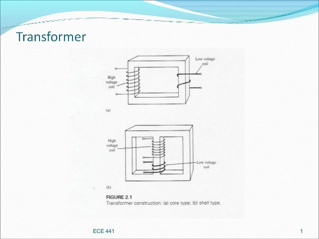
Transformer

ECE 441 1
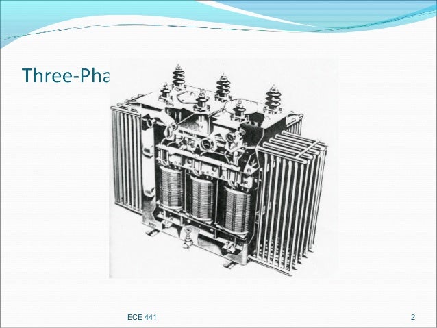
 ECE 441 2
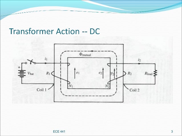
 ECE 441 3
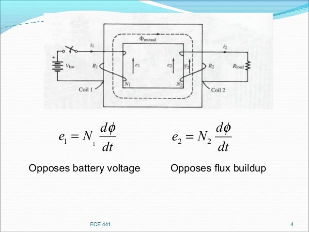
 ECE 441 4
11
d
e N
dt
φ
= 2 2
d
e N
dt
φ
=
Opposes battery voltage Opposes flux buildup
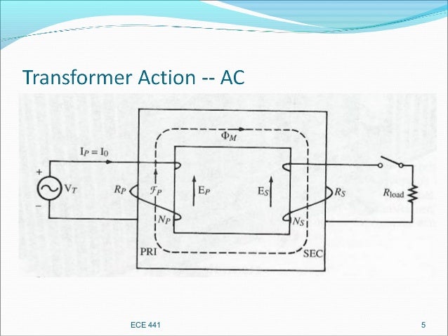
 ECE 441 5
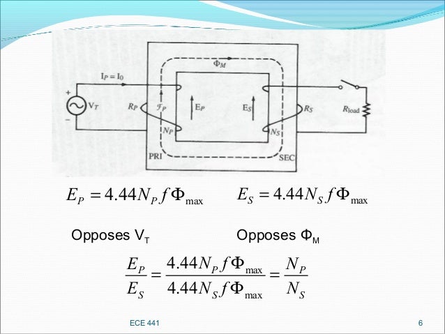
 ECE 441 6
max4.44P PE N f= Φ max4.44S SE N f= Φ
Opposes VT Opposes ΦM
max
max
4.44
4.44
PP P
S S S
N fE N
E N f N
Φ
= =
Φ
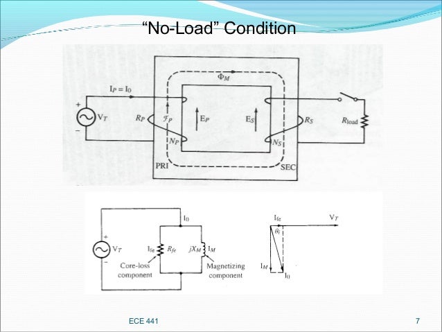
 ECE 441 7
“No-Load” Condition
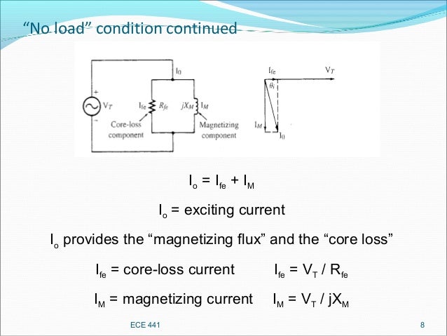
 “No load” condition continued
ECE 441 8
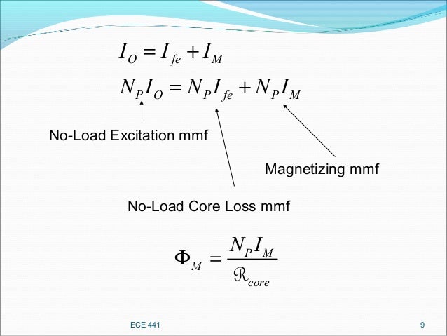
Io = Ife + IM
Io = exciting current
Io provides the “magnetizing flux” and the “co...ECE 441 9
O fe M
P O P fe P M
I I I
N I N I N I
= +
= +
No-Load Excitation mmf
No-Load Core Loss mmf
Magnetizing mmf
P M
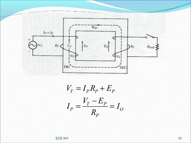
M...ECE 441 10
T P P P
T P
P O
P
V I R E
V E
I I
R
= +
−
= =
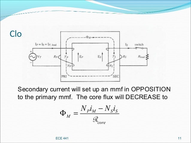
 Close the load switch
P M S S
M
core
N i N i−
Φ =
R
ECE 441 11
Secondary current will set up an mmf in OPPOSITION
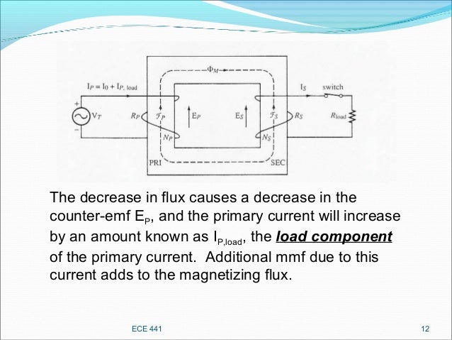
to the p...ECE 441 12
The decrease in flux causes a decrease in the
counter-emf EP, and the primary current will increase
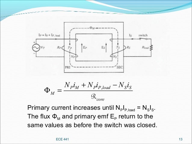
by an amoun...ECE 441 13
,P M P P load S S
M
core
N i N i N i+ −
Φ =
R
Primary current increases until NPIP,load = NSIS.
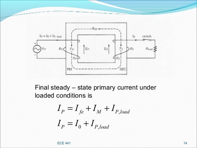
The flux ΦM and...ECE 441 14
Final steady – state primary current under
loaded conditions is
,
0 ,
P fe M P load
P P load
I I I I
I I I
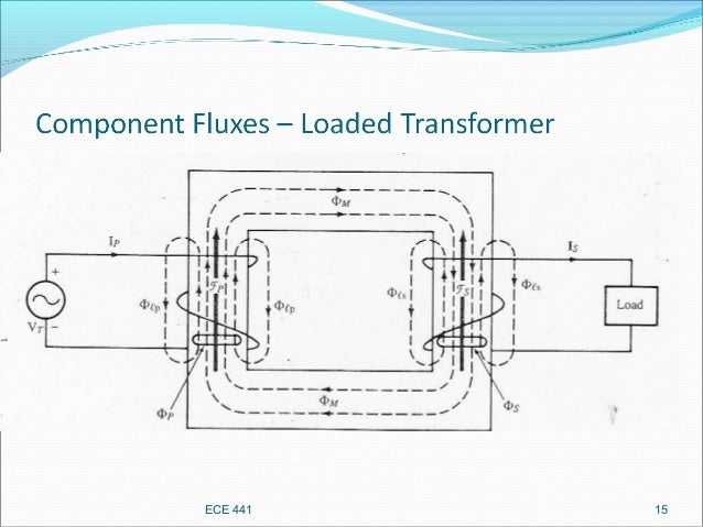
= + ...ECE 441 15
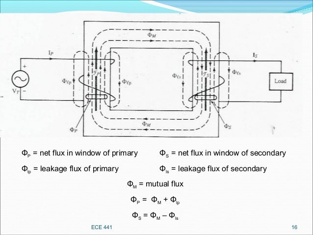
 ECE 441 16
ΦP = net flux in window of primary ΦS = net flux in window of secondary
Φlp = leakage flux of primary Φls = lea...

Posted on April 6, 2018Categories Electrical & Electronics EngineeringLeave a comment on Transformer

Servo System & Servo motor

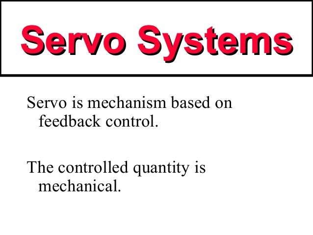
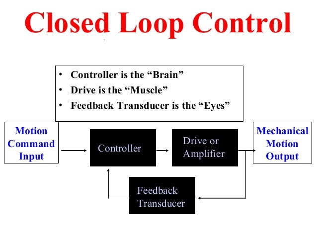
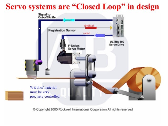
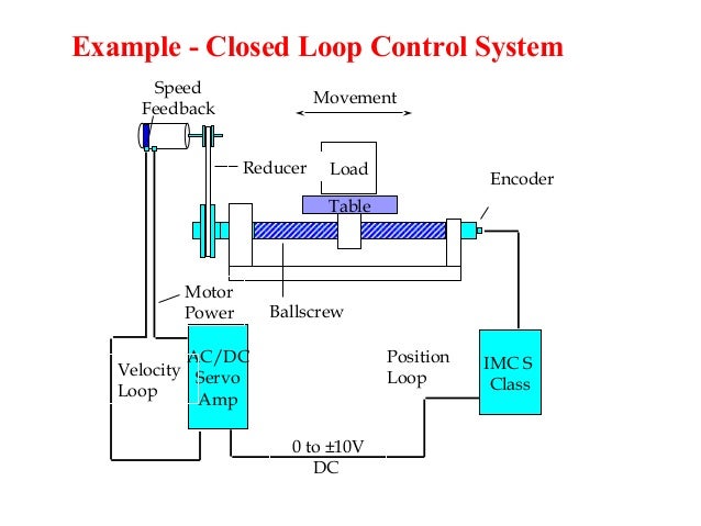
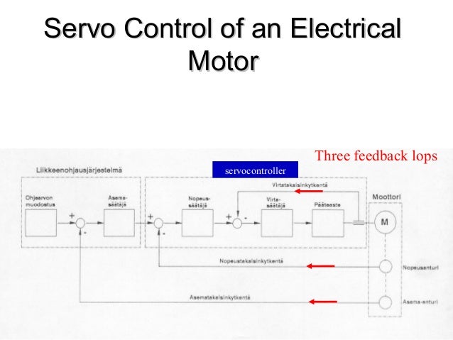
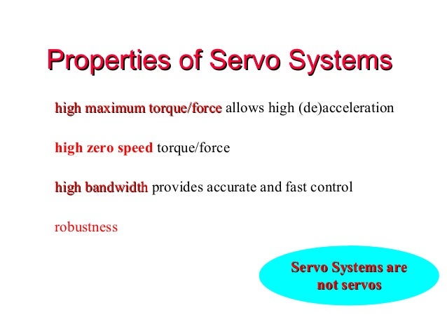
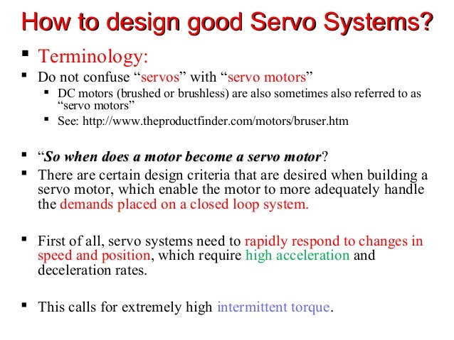
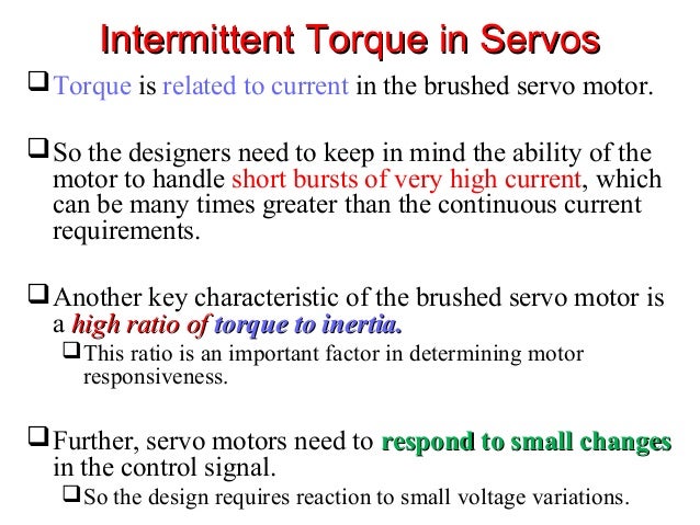
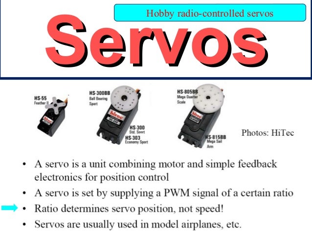
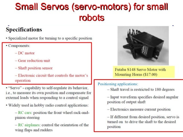
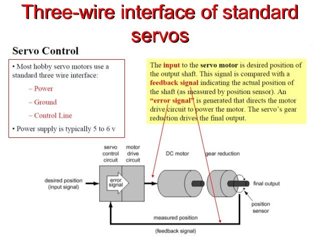
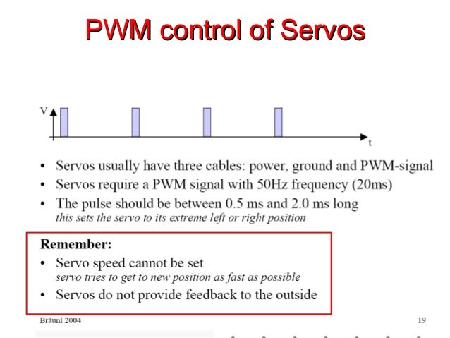
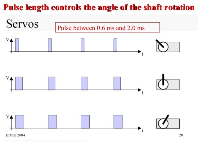
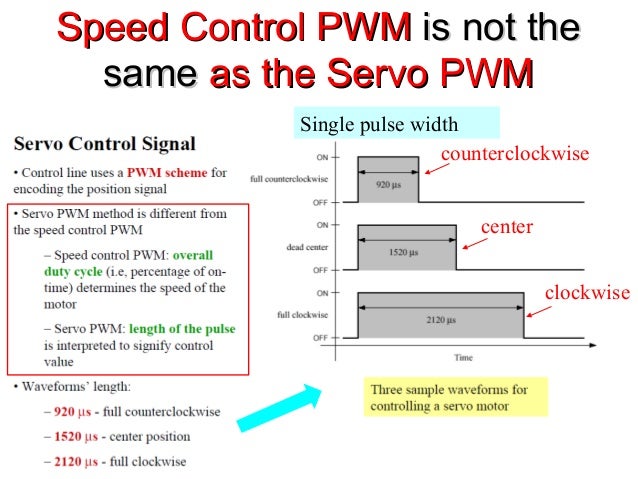
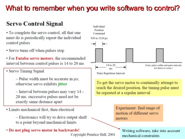
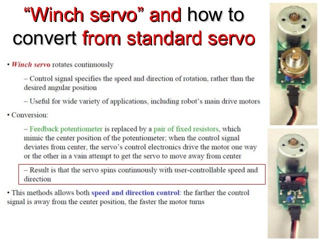
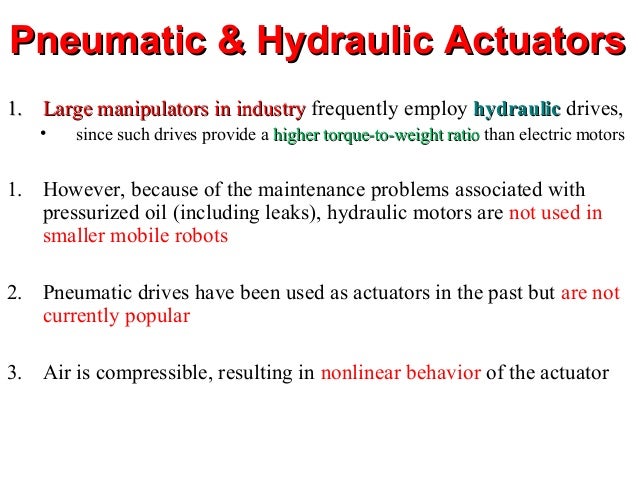
Jussi Suomela HUT/Automation 1 Servo SystemsServo Systems Servo is mechanism based on feedback control. The controlled qua...Your Partner In Productivity Closed Loop Control • Controller is the “Brain” • Drive is the “Muscle” • Feedback Transducer...Your Partner In Productivity • Uses feedback for automatic correction • High performance Servo systems are “Closed Loop” i...Speed Feedback Load Table Movement IMC S Class AC/DC Servo Amp 0 to ±10V DC Position LoopVelocity Loop Encoder Ballscrew R...Jussi Suomela HUT/Automation 5 Servo Control of an ElectricalServo Control of an Electrical MotorMotor servocontroller Thr...Jussi Suomela HUT/Automation 6 Properties of Servo SystemsProperties of Servo Systems high maximum torque/forcehigh maximu...How to design good Servo Systems?How to design good Servo Systems?  Terminology:  Do not confuse “servos” with “servo mo...Intermittent Torque in ServosIntermittent Torque in Servos Torque is related to current in the brushed servo motor. So t...ServosServos Hobby radio-controlled servos  Small Servos (servo-motors) for smallSmall Servos (servo-motors) for small robotsrobots Positioning applications:  Three-wire interface of standardThree-wire interface of standard servosservos  PWM control of ServosPWM control of Servos  Pulse between 0.6 ms and 2.0 ms Pulse length controls the angle of the shaft rotationPulse length controls the angle of th...Speed Control PWMSpeed Control PWM is not theis not the samesame as the Servo PWMas the Servo PWM counterclockwise center ...What to remember when you write software to control?What to remember when you write software to control? Writing software,...““Winch servo” andWinch servo” and how tohow to convertconvert from standard servofrom standard servo  Pneumatic & Hydraulic ActuatorsPneumatic & Hydraulic Actuators 1.1. Large manipulators in industryLarge manipulators in in...

Posted on April 6, 2018March 4, 2020Categories Special Electric MachineLeave a comment on Servo System & Servo motor

Stepper Motor

Applied Control
Systems
Stepper Motors
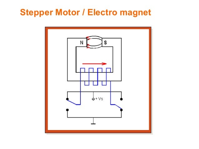
 Stepper Motor / Electro magnet
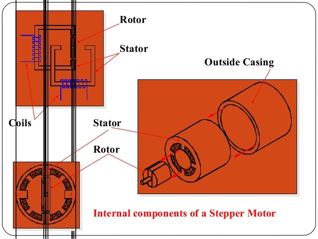
 Rotor
Stator
Coils
2
1
S
N
1
2
Outside Casing
Stator
Rotor
Internal components of a Stepper Motor
 2 2
1
N
S
1
S
N
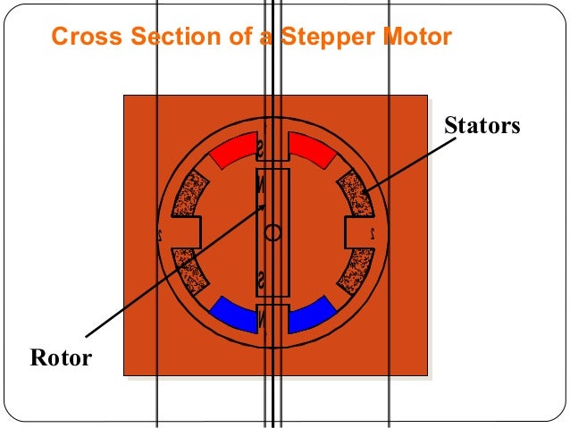
Stators
Rotor
Cross Section of a Stepper Motor
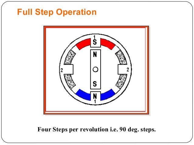
 Four Steps per revolution i.e. 90 deg. steps.
Full Step Operation
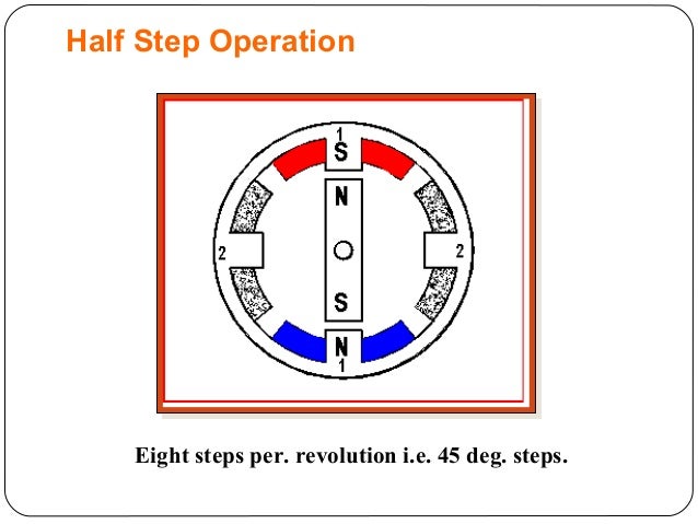
 Eight steps per. revolution i.e. 45 deg. steps.
Half Step Operation
 2 2
1
1
S
N
S
N
NN
S S
1
a b
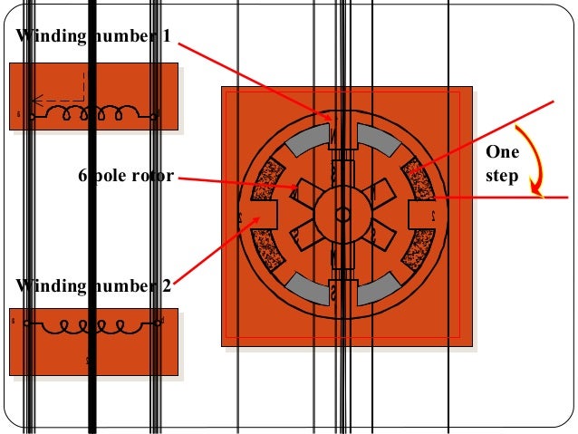
Winding number 1
2
a b
Winding number 2
One
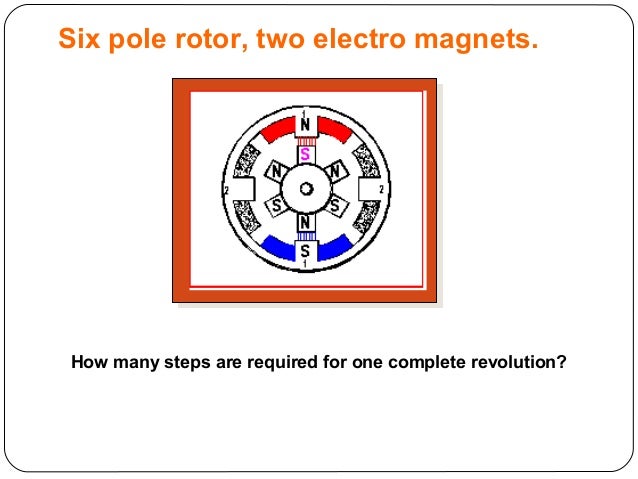
step6 pole rotor
 How many steps are required for one complete revolution?
Six pole rotor, two electro magnets.
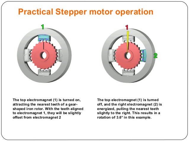
 The top electromagnet (1) is turned on,
attracting the nearest teeth of a gear-
shaped iron rotor. With the teeth aligned
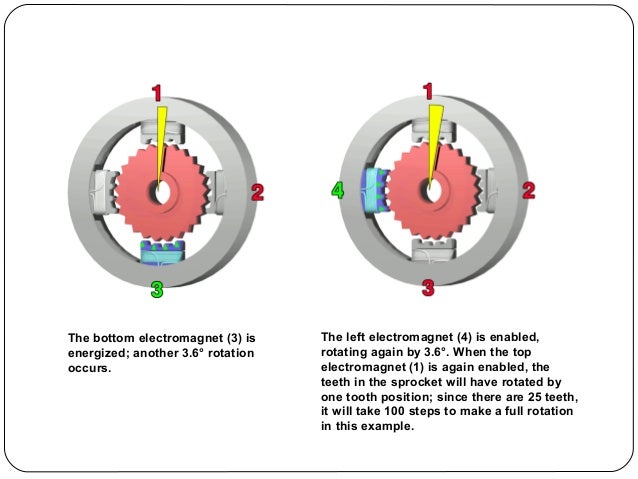
...The bottom electromagnet (3) is
energized; another 3.6° rotation
occurs.
The left electromagnet (4) is enabled,
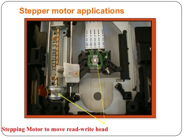
rotating a...Stepping Motor to move read-write head
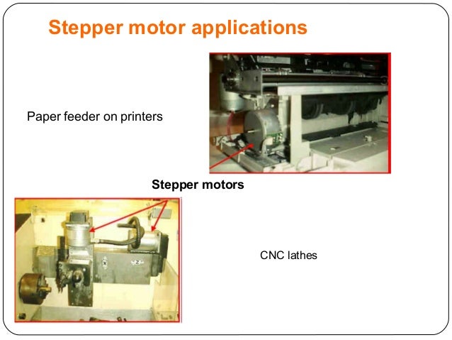
Stepper motor applications
 Paper feeder on printers
CNC lathes
Stepper motors
Stepper motor applications
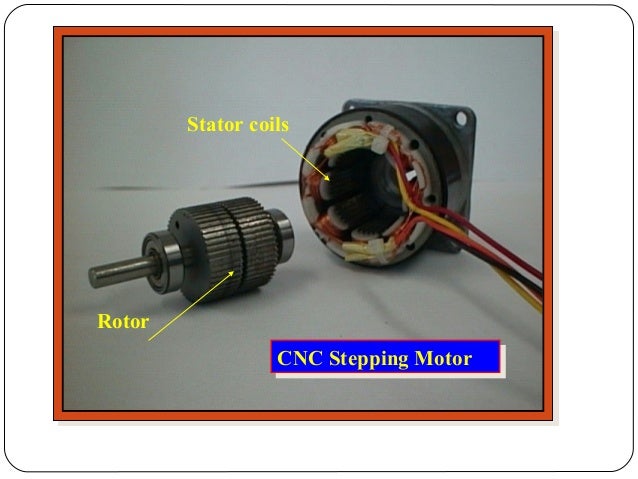
 Rotor
Stator coils
CNC Stepping MotorCNC Stepping Motor
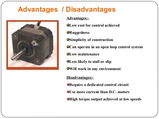
 Advantages:-
Low cost for control achieved
Ruggedness
Simplicity of construction
Can operate in an open loop control syste...Step 1 0 0 1 1
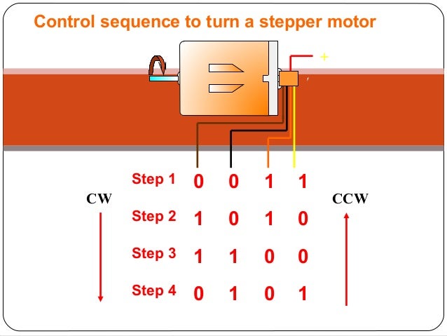
Step 2 1 0 1 0
Step 3 1 1 0 0
Step 4 0 1 0 1
+
CW CCW
Control sequence to turn a stepper motor
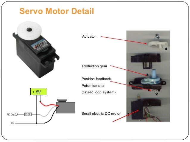
 Servo Motor Detail
+ 5V
Actuator
Reduction gear
Position feedback
Potentiometer
(closed loop system)
Small electric DC mot...

Posted on April 6, 2018Categories Electrical & Electronics EngineeringLeave a comment on Stepper Motor

Universal Motor

UniversalMotor
1
Universal Motor
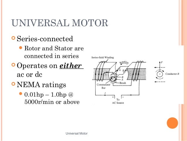
 UNIVERSAL MOTOR
 Series-connected
Rotor and Stator are
connected in series
 Operates on either
ac or dc
 NEMA ratings
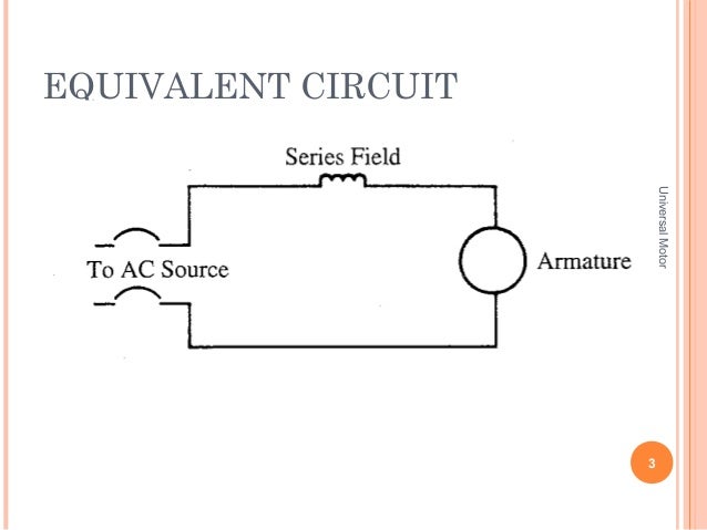
...EQUIVALENT CIRCUIT
3
UniversalMotor
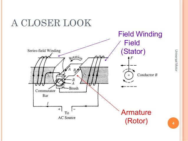
 A CLOSER LOOK
4
UniversalMotor
Armature
(Rotor)
Field Winding
Field
(Stator)
 UniversalMotor
5
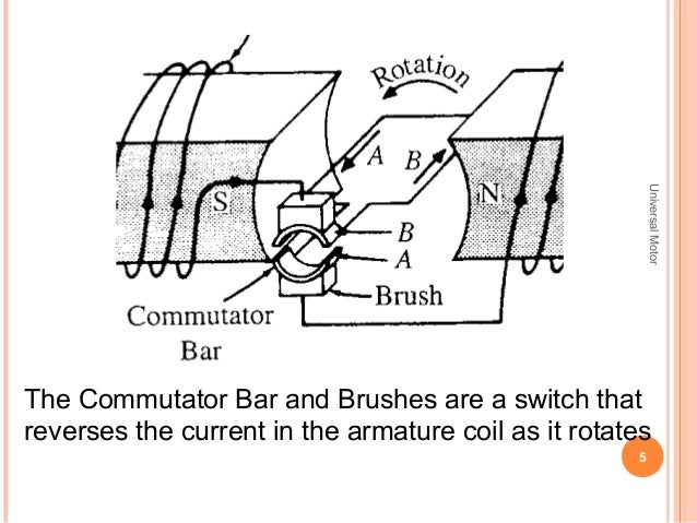
The Commutator Bar and Brushes are a switch that
reverses the current in the armature coil as it rotates
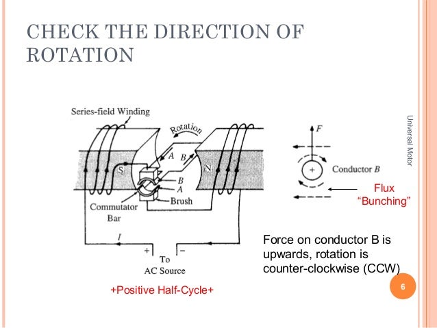
 CHECK THE DIRECTION OF
ROTATION
6
UniversalMotor
Force on conductor B is
upwards, rotation is
counter-clockwise (CCW)
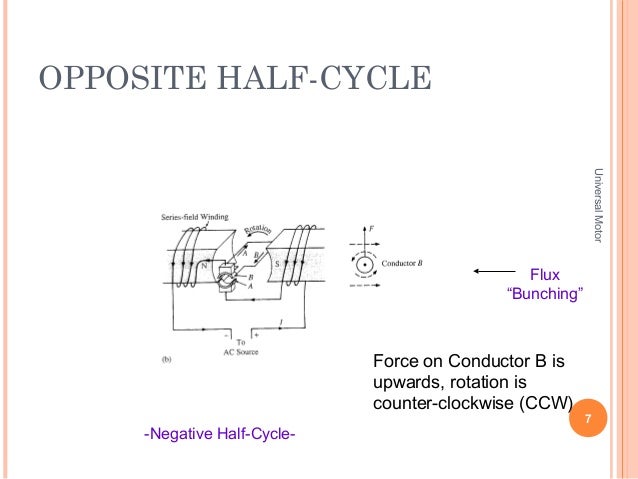
Flux...OPPOSITE HALF-CYCLE
7
UniversalMotor
Force on Conductor B is
upwards, rotation is
counter-clockwise (CCW)
Flux
“Bunching”
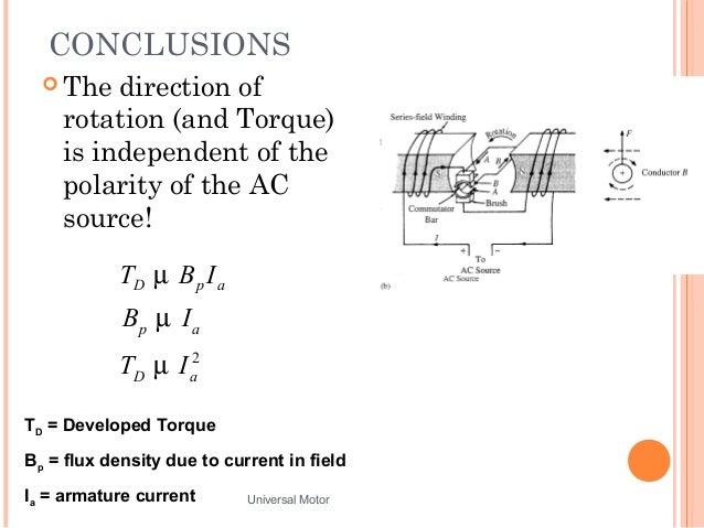
...CONCLUSIONS
 The direction of
rotation (and Torque)
is independent of the
polarity of the AC
source!
Universal Motor 8
2
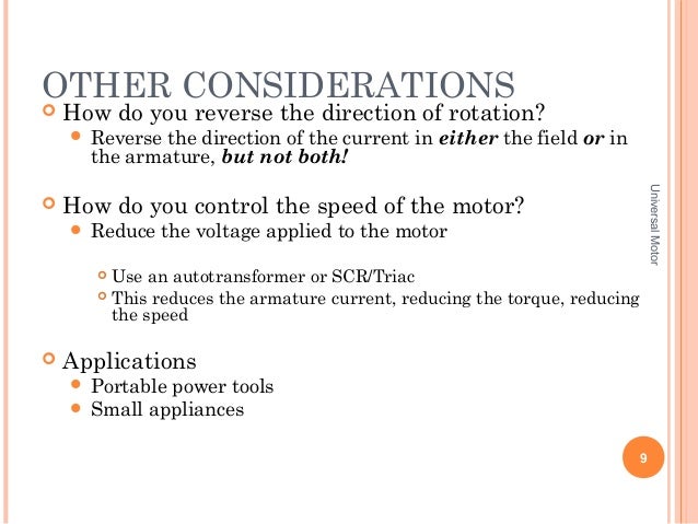
...OTHER CONSIDERATIONS
 How do you reverse the direction of rotation?
 Reverse the direction of the current in either the ...

Posted on April 6, 2018Categories Electrical & Electronics EngineeringLeave a comment on Universal Motor

DC machine (Generator and Motor)

General arrangement
of a four-pole d.c. machine
Concept of simple loop generator
Working
simple loop generator
Important – right hand rule for generator
One revolution of a coil
Slip rings are replaced by Split rings
Action of commutator
• The emf induced in the armature conductors of a dc
generator is alternating in nature. It is rectif...
Essential parts of DC machine
Yoke
Pole cores and Pole Shoes
Pole COILs
Pole COILs
Field winding
Armature Core
Commutator
A commutator is a mechanical rectifier which converts the alternating
voltage generated in the armature winding...
Armature and armature
windings with commutator
brushes and bearings
• The purpose of brushes is to ensure electrical
connections between the rotating commutator
and stat...
• The brush pressure is adjusted by means of adjustable
springs; If the brush pressure is very large, the
friction produce...
Bearings
• It is a device which gives free and smooth
rotation to the armature.
• The function of the bearing is to suppor...
Shaft
• The shaft is made of mild steel. The shaft is
used to transfer mechanical power from or to
the machine.
• The rota...
Brushes and
commutator
Schematic representations of a dc machine. (a) Schematic arrangement. (b) Circuit
representation.
Lap and Wave Windings
Simplex wave winding
• Yc≈2, the coils under consecutive pole pairs
will be joined together in series their emfs.
• After ...
Armature winding
Prerequisite
Pitch & POLE PITCH
COIL and winding element
Single turn Multi
turn
Coil Span or Coil Pitch (YS)
Coil pitch is 3/4th –
Fractional Pitch
ARMATURE WINDING
 Pole pitch (YP)
= No. of conductors per pole.
 Front Pitch (YF)
= No. of conductors between two
conduc...
Lap
winding
Wave
winding
Example of developed lap
winding
Single layer winding
double layer winding
Classification of DC machine:
DC motor
DC generator
DC
MACHINE
STATOR
POLE
FIELD
WINDING
YOKE
ROTOR
ARMATURE
ARMATURE
WINDING
COMMUTAT
OR
BRUSH
Revise the entire thing
DC
GENERATOR
SEPERATEL
Y EXCITED
SELF
EXCITED
SHUNT SERIES
COMPOUN
D
CUMULATI
VE
DIFFERENTI
AL
MOTOR
SEPERATEL
Y EXCITED
S...
When large magnetomotive force is applied to
the core and then removed. The flux in the
core doesn't reach zero. Instead, ...
E.M.F. EQUATION
Let
Ø=flux/pole in Wb
Z = total number of armature
conductors
P = number of poles
A = number of parallel p...
BRUSH
No load curve for self excited generator
Voltage build up in DC generator
Voltage build up process
Critical field resistance
Losses in DC machine
DC MOTOR
Basic Principle
It should be noted that the function of a commutator in the motor is
the same as in a generator. By revers...
Comparison of Generator Action and Motor Action
Force is in opposite to the armature
rotation – magnetic drag
Force of Rubber Band on Catapult
Significance of back emf
Voltage equation of motor
Torque equation of dc motor
• But first of all What is torque? By the term torque is
meant the turning or twisting moment...
Armature torque of a motor
SHAFT torque of a motor
Speed of a d.c. motor
Characteristics of motor
Characteristics of DC series motor
Ta/Ia Characteristics
Characteristics of DC series motor
N/Ia Characteristics
 Characteristics of DC series motor
N/Ta or mechanical characteristics
 Characteristics of DC shunt motor
Ta/Ia
Characteristics
For dc shunt motors;
Ia=IL-Ish,
Ish=V/Rsh;
V=Eb+IaRa
From second e...Characteristics of DC SHUNT motor
N/Ia Characteristics
 Characteristics of DC shunt motor
N/Ta or mechanical characteristics
 Characteristics of compound motors
Cumulative-compound Motors
Differential-compound Motors
 Characteristics of compound motors with comparison
 Comparison of Shunt and series motors
• Shunt Motors:
(a) speed of a shunt motor is sufficiently constant.
(b) for the sam...Comparison of Shunt and series motors CONT…
• Series motor: These motors
1. have a relatively huge starting torques.
2. ha...Where not used????
 Power Stages in DC machines
DC Generator
 Condition for max. Efficiency
 Power Stages in DC machines
DC motor
 DC motor speed control
dc shunt motor
 NEED
• It is obvious that the speed can be controlled by varying ;
(i) flux/pole, f (Flux Control)
(ii) resistance Ra of a...Variation of Flux or Flux Control Method:
• It is seen from above that N ∝ 1/f. By decreasing the
flux, the speed can be ...Cont.
• As R is increases by sliding contact from Ish
decreases; Increases in motor speed N.
• So as flux increases Speed ...Rheostatic Control or Armature Control Technique
• This method is used when speeds below the no-load
speed are required.
•...voltage is normally constant, the voltage across
the armature is varied by inserting a variable
rheostat or resistance
 Additional control resistance
 Armature control technique
 Ward-Leonard System
• This system is used where an unusually wide (upto 10 : 1) and
very sensitive speed control is requir...Ward-Leonard System
• The motor M2 runs at an approximately constant speed. The
output voltage of G is directly fed to the...DC motor speed control
dc series motor
 Field Diverter Method
• Variable R is connected across field winding called field
diverter.
• Parallel path for the field ...Armature Diverter
 Starters of DC machine
Need of starters
 Need of starters
Cont....
 Shunt motor starter
Three point starter
 Four point starter
 No of coils and commutator segment – winding diagarm
 Dc machine (B.L.Thareja)Dc machine (B.L.Thareja)Dc machine (B.L.Thareja)Dc machine (B.L.Thareja)Dc machine (B.L.Thareja)Dc machine (B.L.Thareja)Dc machine (B.L.Thareja)Dc machine (B.L.Thareja)Dc machine (B.L.Thareja)Dc machine (B.L.Thareja)Dc machine (B.L.Thareja)Dc machine (B.L.Thareja)Dc machine (B.L.Thareja)Dc machine (B.L.Thareja)Dc machine (B.L.Thareja)Dc machine (B.L.Thareja)Dc machine (B.L.Thareja)Dc machine (B.L.Thareja)Dc machine (B.L.Thareja)Dc machine (B.L.Thareja)Dc machine (B.L.Thareja)Dc machine (B.L.Thareja)Dc machine (B.L.Thareja)Dc machine (B.L.Thareja)Dc machine (B.L.Thareja)Dc machine (B.L.Thareja)Dc machine (B.L.Thareja)Dc machine (B.L.Thareja)Dc machine (B.L.Thareja)Dc machine (B.L.Thareja)Dc machine (B.L.Thareja)Dc machine (B.L.Thareja)Dc machine (B.L.Thareja)

Posted on April 3, 2018Categories Electrical & Electronics EngineeringLeave a comment on DC machine (Generator and Motor)

Principle of AC Transmission

Principle of AC Transmission

Schematic of AC system

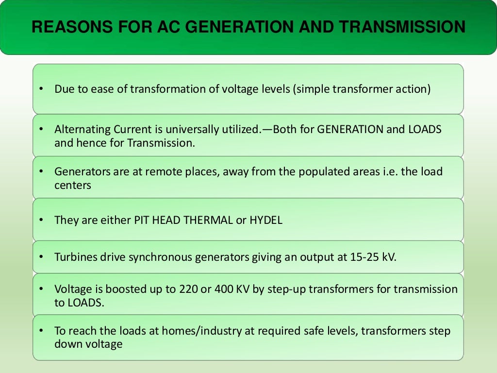
REASONS FOR AC GENERATION AND TRANSMISSION

• Due to ease of transformation of voltage levels (simple transformer action)
...

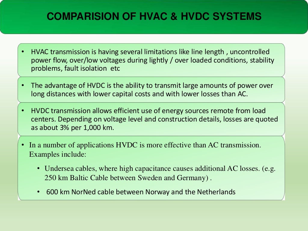
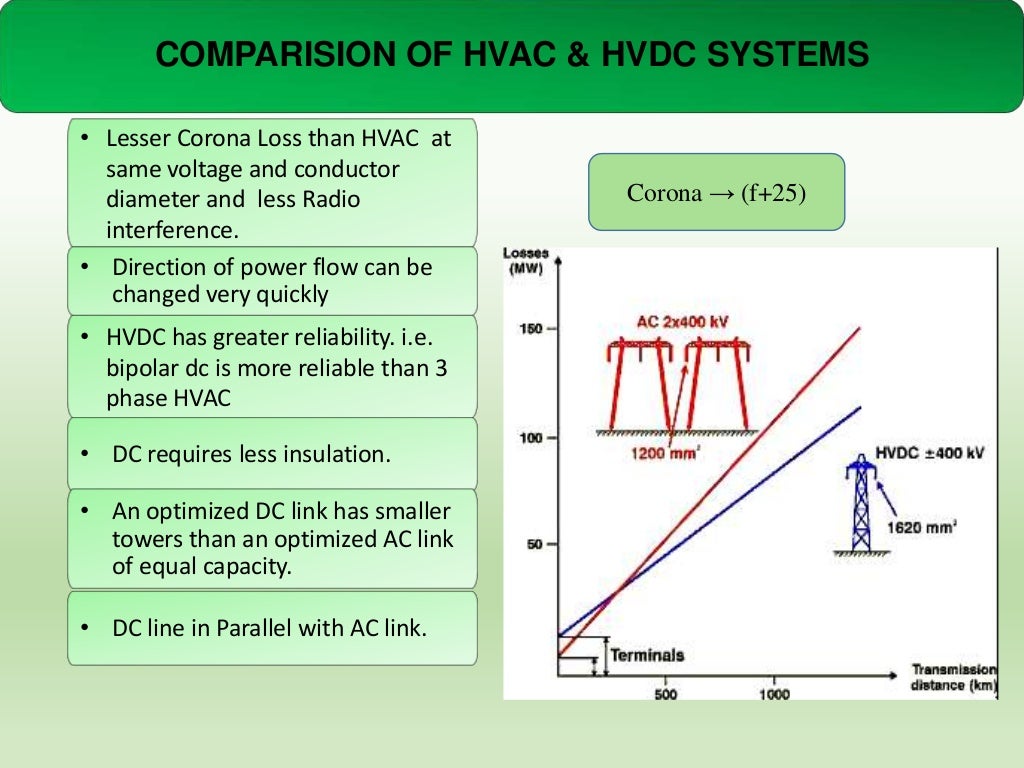
COMPARISION OF HVAC & HVDC SYSTEMS
• HVAC transmission is having several limitations like line length , uncontrolled
power...
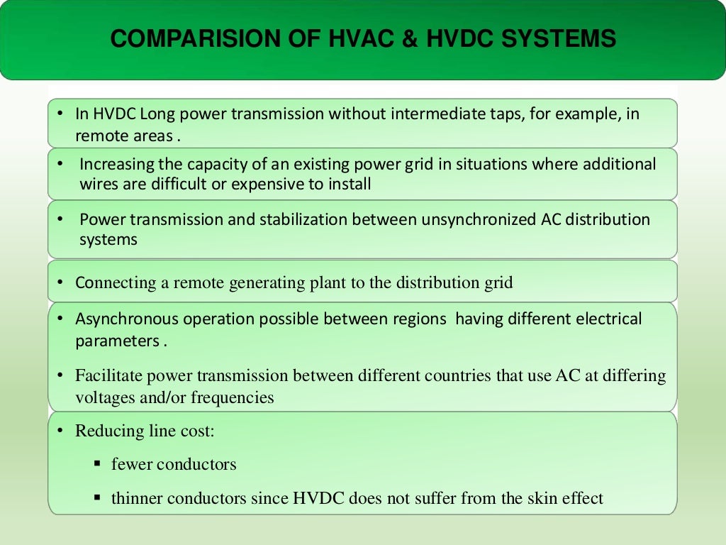
COMPARISION OF HVAC & HVDC SYSTEMS
• In HVDC Long power transmission without intermediate taps, for example, in
remote are...
COMPARISION OF HVAC & HVDC SYSTEMS
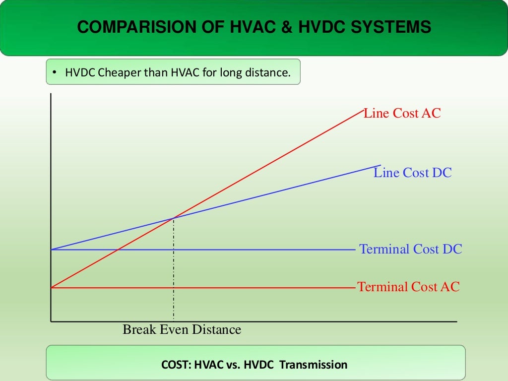
• HVDC Cheaper than HVAC for long distance.

Line Cost AC

Line Cost DC

Terminal Cost ...
COMPARISION OF HVAC & HVDC SYSTEMS

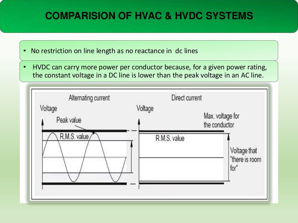
• No restriction on line length as no reactance in dc lines
• HVDC can carry more powe...
COMPARISION OF HVAC & HVDC SYSTEMS

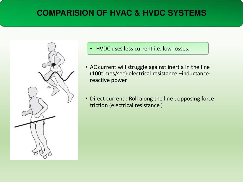
• HVDC uses less current i.e. low losses.
• AC current will struggle against inertia i...
COMPARISION OF HVAC & HVDC SYSTEMS

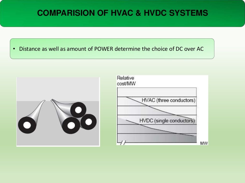
• Distance as well as amount of POWER determine the choice of DC over AC
COMPARISION OF HVAC & HVDC SYSTEMS

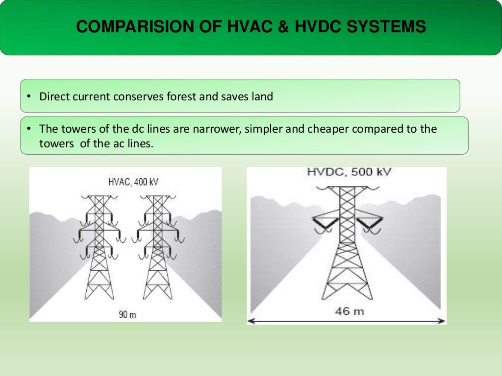
• Direct current conserves forest and saves land

• The towers of the dc lines are nar...
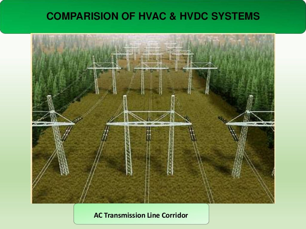
COMPARISION OF HVAC & HVDC SYSTEMS

AC Transmission Line Corridor
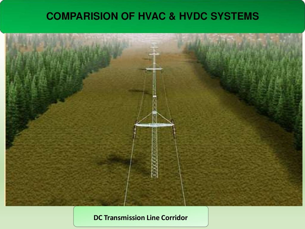
COMPARISION OF HVAC & HVDC SYSTEMS

DC Transmission Line Corridor
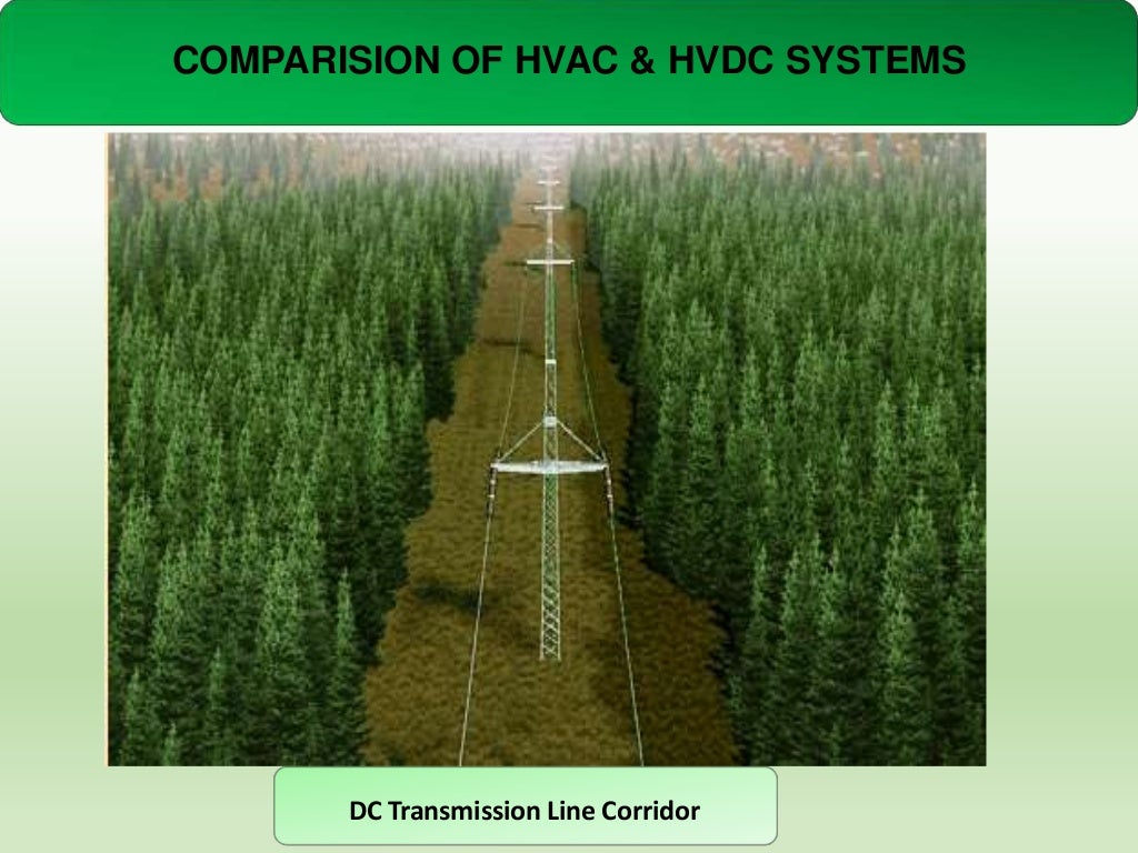
COMPARISION OF HVAC & HVDC SYSTEMS

DC Transmission Line Corridor
COMPARISION OF HVAC & HVDC SYSTEMS
• Lesser Corona Loss than HVAC at
same voltage and conductor
diameter and less Radio
in...

Posted on March 31, 2018Categories Electrical & Electronics EngineeringLeave a comment on Principle of AC Transmission

Dc as a means of transmission

DC transmission has been possible with the beginning of
1. High power/ high current capability thyristor.
2. Fast acting computerized controls

Since our primary source of power is AC, the three basic steps are
1. Convert AC into DC (rectifier)
2. Transmit DC
3. Convert DC into AC
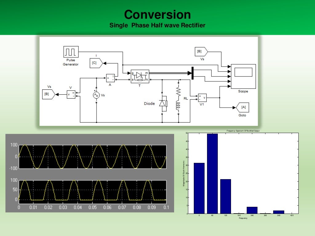
Conversion
Single Phase Half wave Rectifier

Frequency Specturm Of Rectified Output
50

45

40

Magnitude Of Each Hormonic...
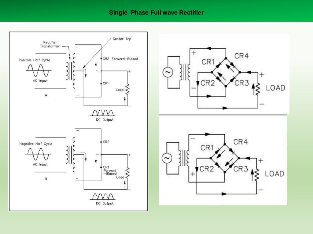
Single Phase Full wave Rectifier

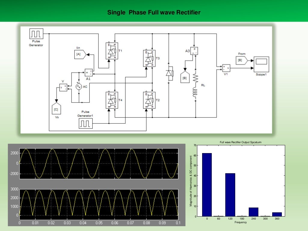
Single Phase Full wave Rectifier

Full wave Rectifier Output Spceturm

Magnitude of Harmonics & DC component

70

60

50

...
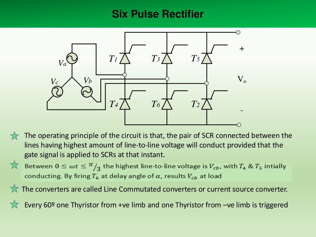
Six Pulse Rectifier
+

T1

Va
Vc

T3

T5
Vo

Vb

T4

T6

T2

-

The operating principle of the circuit is that, the pair o...
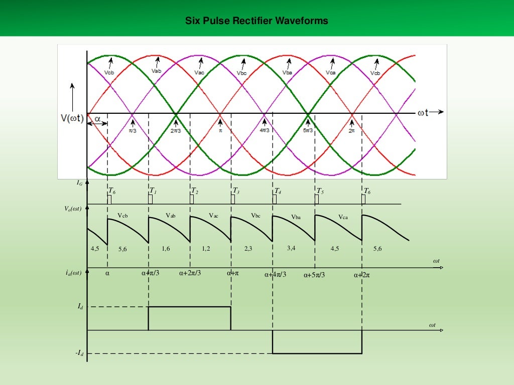
Six Pulse Rectifier Waveforms

IG

T6

T1

T2

T3

T4

T5

T6

Vo(ωt)
Vcb

4,5

Vab

Vac

1,6

5,6

Vbc

1,2

Vba

Vca

3,...
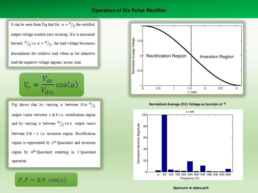
Operation of Six Pulse Rectifier

0.5

Rectification Region

0

Inversion Region

-0.5

-1

0

0.5

1

1.5
(rad)

2

2.5

...
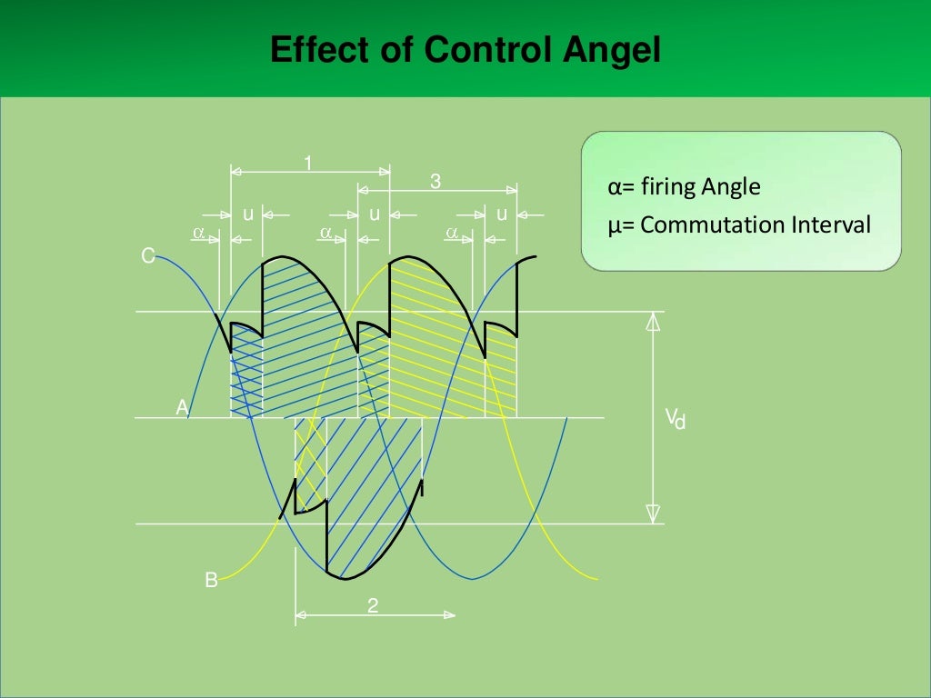
Effect of Control Angel
1
u

3
u

u

α= firing Angle
μ= Commutation Interval

C

A

Vd

B
2
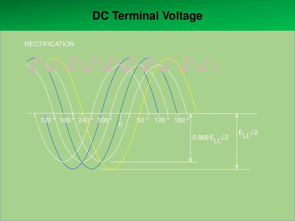
DC Terminal Voltage
RECTIFICATION

120 º 180 º 240 º 300 º

0

60 º 120 º 180 º
0.866 E . 2
LL

E . 2
LL
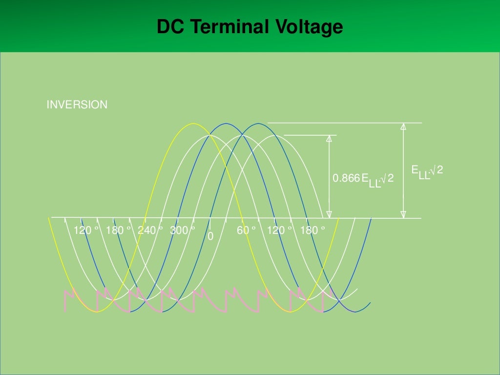
DC Terminal Voltage

INVERSION

0.866 E . 2
LL

120 º 180 º 240 º 300 º

0

60 º 120 º 180 º

E . 2
LL
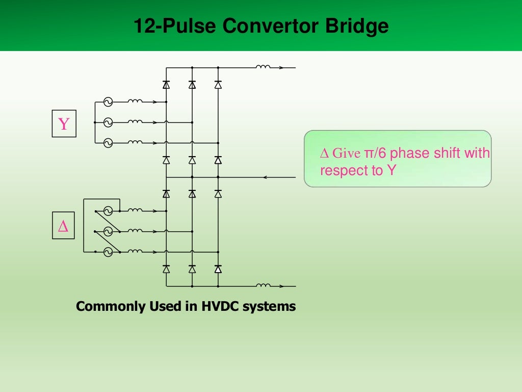
12-Pulse Convertor Bridge

Y
Give π/6 phase shift with
respect to Y

Commonly Used in HVDC systems
12-Pulse Convertor Bridge

Y
Give π/6 phase shift with
respect to Y

Commonly Used in HVDC systems
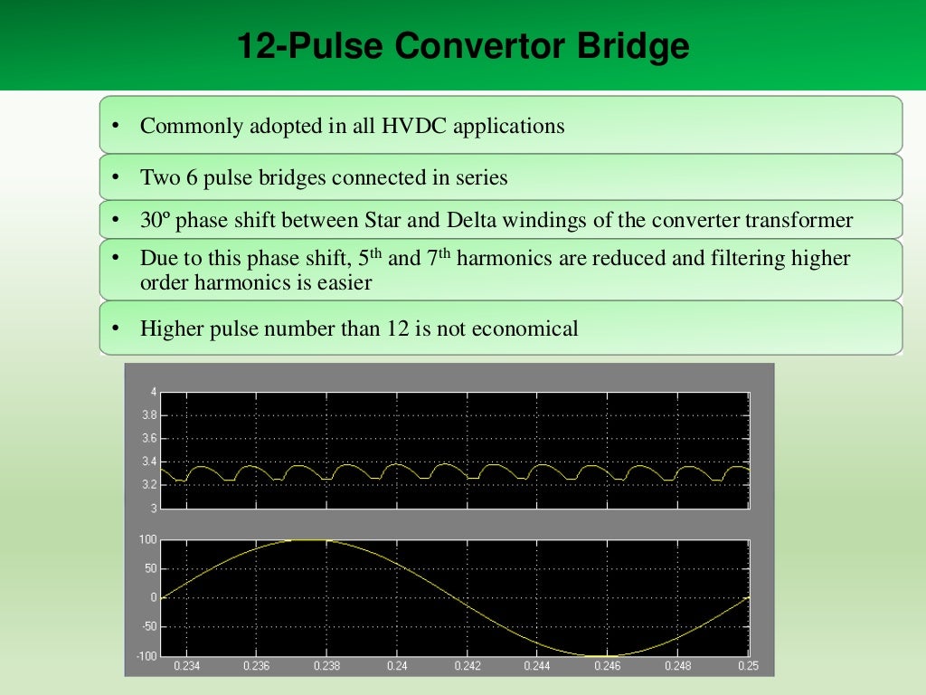
12-Pulse Convertor Bridge
• Commonly adopted in all HVDC applications
• Two 6 pulse bridges connected in series
• 30º phas...
12-Pulse Convertor Bridge
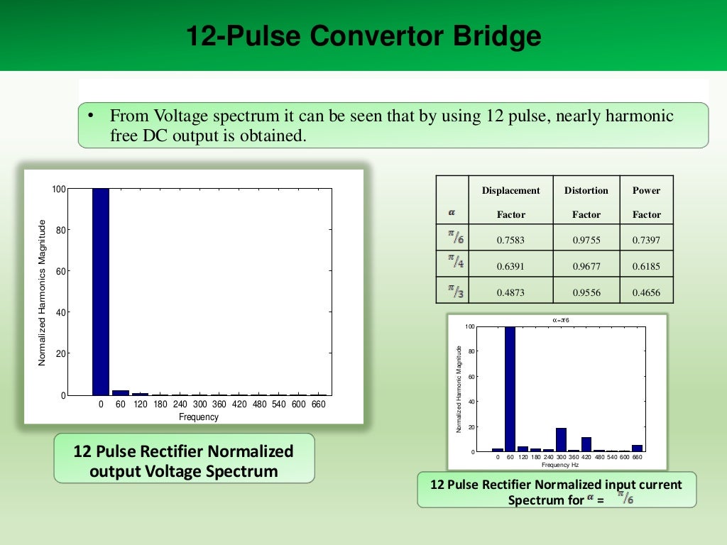
• From Voltage spectrum it can be seen that by using 12 pulse, nearly harmonic
free DC output is...
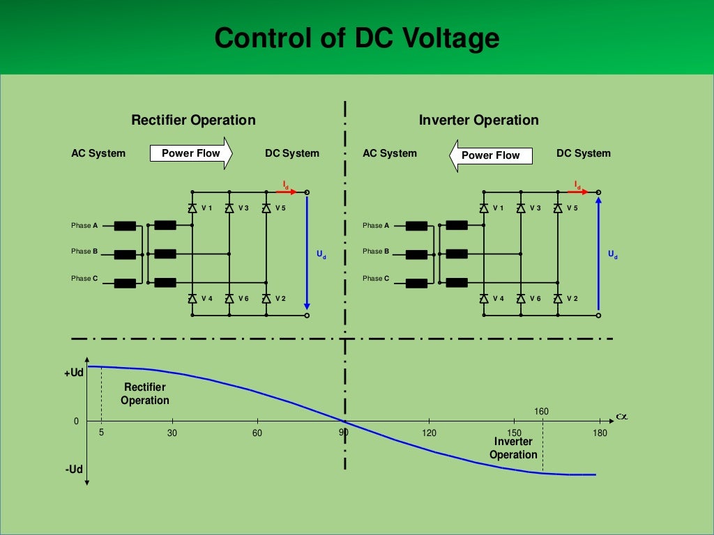
Control of DC Voltage
Rectifier Operation
AC System

Power Flow

Inverter Operation
DC System

AC System

DC System

Power...
Relationship of DC Voltage Ud and Firing Angle α
Rect.

Limit

+Ud

Rectifier
Operation
160

0
5

30

90

60

120

150

18...
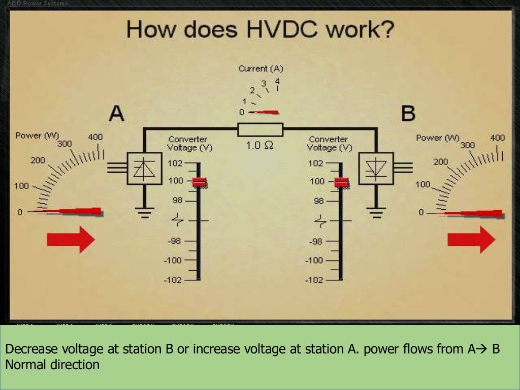
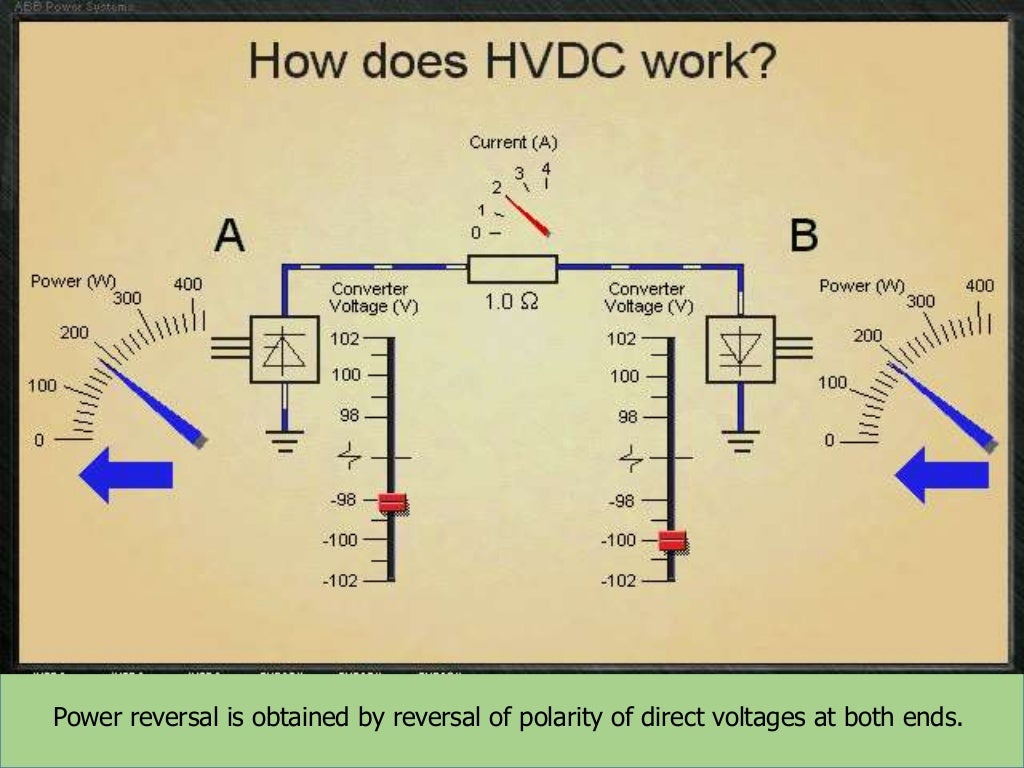
Decrease voltage at station B or increase voltage at station A. power flows from A B Normal
direction

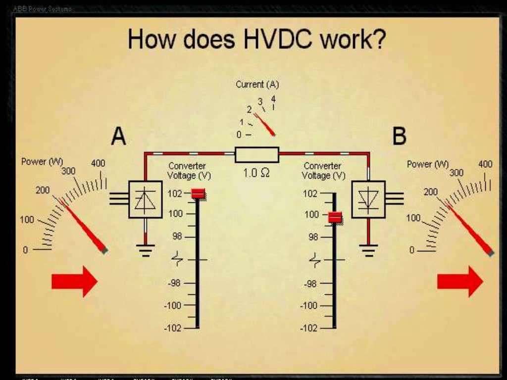
Decrease voltage a...
Power reversal is obtained by reversal of polarity of direct voltages at both ends.
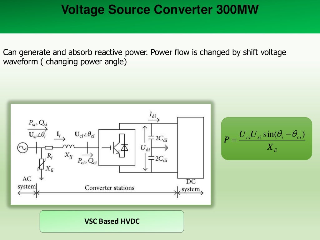
Voltage Source Converter 300MW
Can generate and absorb reactive power. Power flow is changed by shift voltage
waveform ( c...
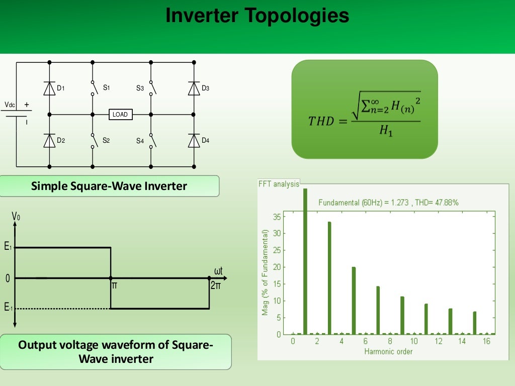
Inverter Topologies

D1

S1

S3

D3

S4

D4

Vdc
LOAD

D2

S2

Simple Square-Wave Inverter
V0
E1
0

π

ωt
2π

E-1

Output ...
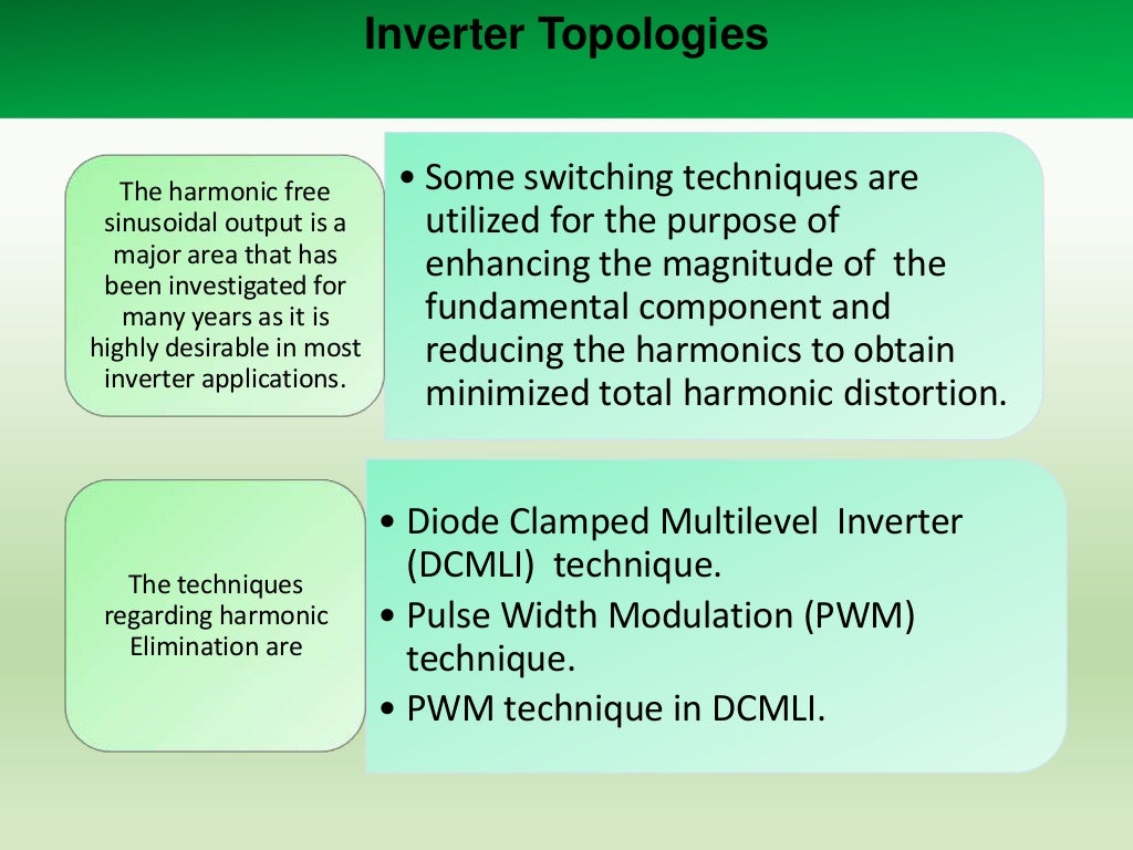
Inverter Topologies

The harmonic free
sinusoidal output is a
major area that has
been investigated for
many years as it i...
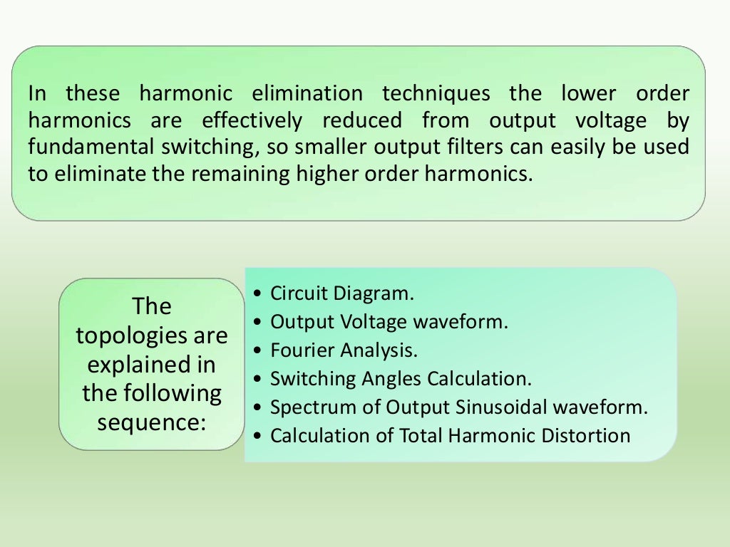
In these harmonic elimination techniques the lower order
harmonics are effectively reduced from output voltage by
fundamen...
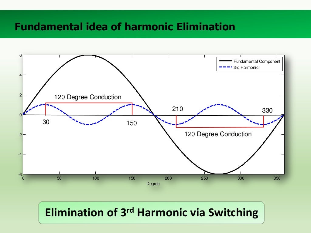
Fundamental idea of harmonic Elimination
6
Fundamental Component
3rd Harmonic
4

2

120 Degree Conduction
210

330

0

30
...
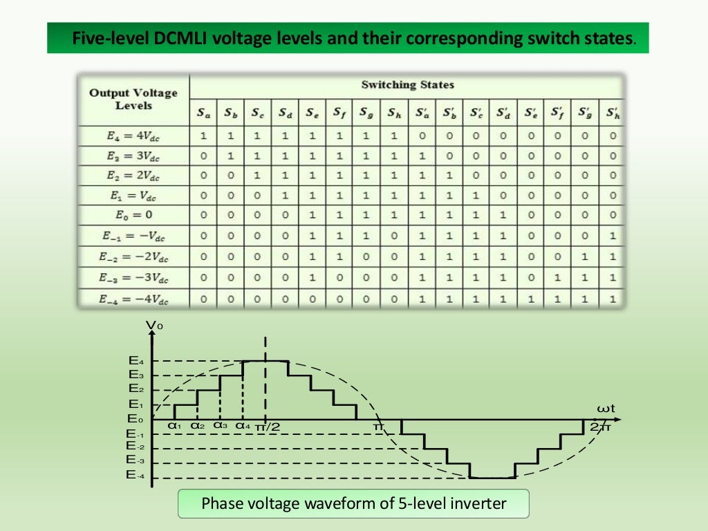
Diode Clamped Multilevel Inverter (DCMLI)
E4
Sa

S'e
Vdc

Da

Sb

Db

Sc

De

S'f

E3

Df

S'g

Vdc

Dc

Sd

Dg

S'h

A

L...
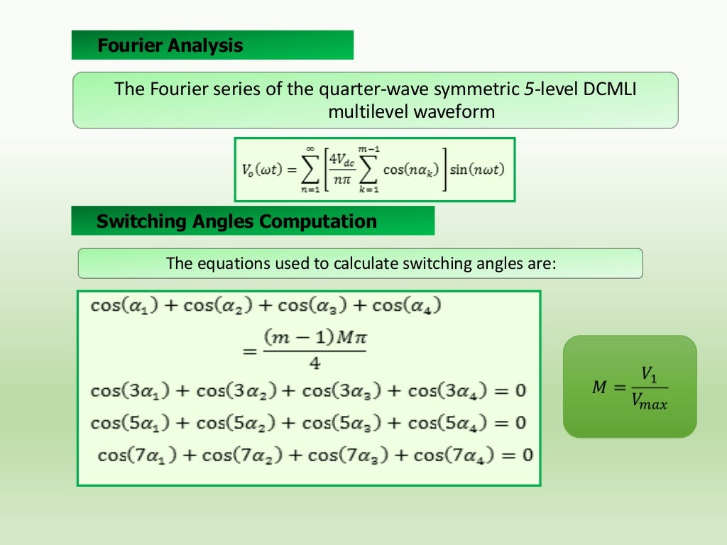
Fourier Analysis

The Fourier series of the quarter-wave symmetric 5-level DCMLI
multilevel waveform

Switching Angles Com...
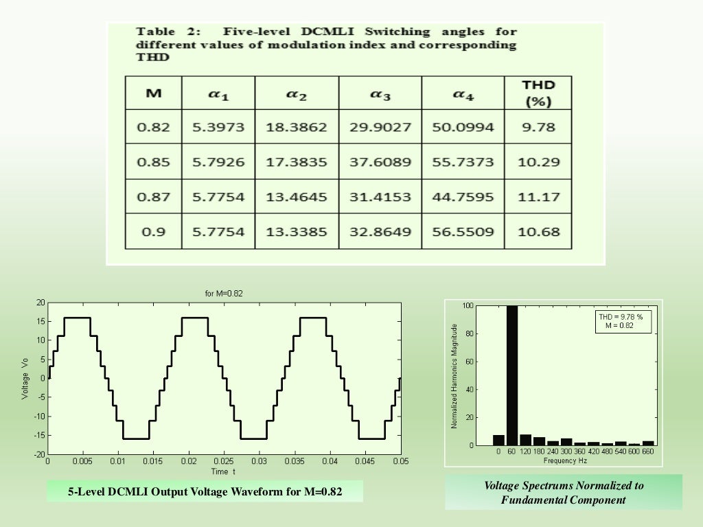
5-Level DCMLI Output Voltage Waveform for M=0.82

Voltage Spectrums Normalized to
Fundamental Component

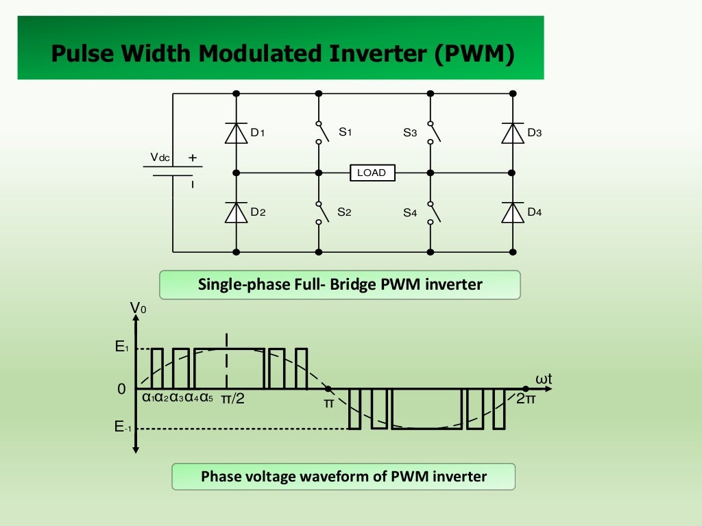
Pulse Width Modulated Inverter (PWM)

S1

D1

S3

D3

S4

D4

Vdc
LOAD

D2

S2

Single-phase Full- Bridge PWM inverter
V0
...
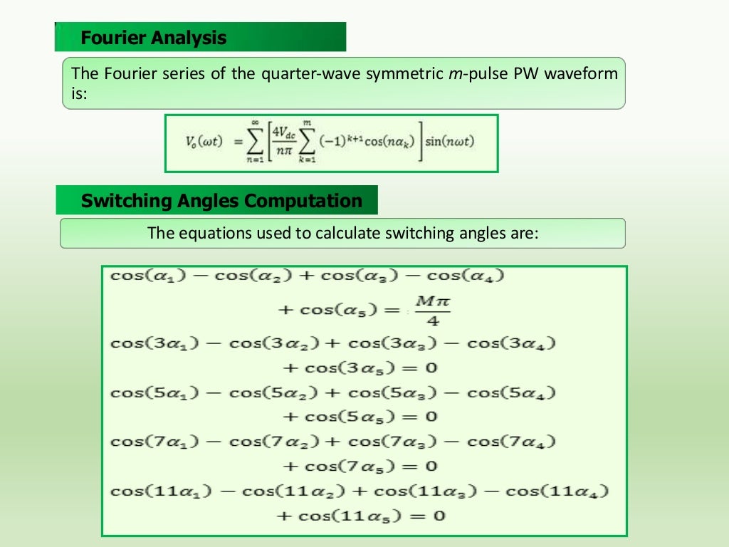
Fourier Analysis
The Fourier series of the quarter-wave symmetric m-pulse PW waveform
is:

Switching Angles Computation
Th...
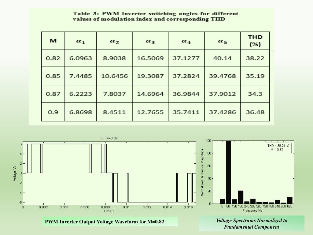
PWM Inverter Output Voltage Waveform for M=0.82

Voltage Spectrums Normalized to
Fundamental Component
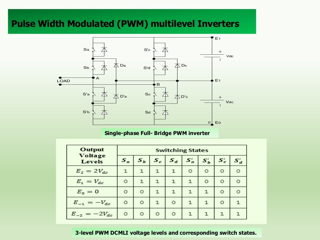
Pulse Width Modulated (PWM) multilevel Inverters
E1
Sa

S'c
Vdc

Da

Sb

Dc

S'd

A

LOAD

E1
B

S'a

D'a

Sc

D'c
Vdc

S'...
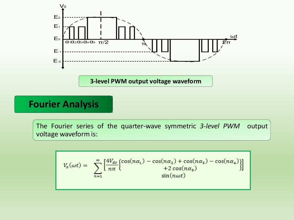
V0
E2
E1
E0

α1α2 α3 α4 α5 π/2

π

ωt
2π

E-1
E-2

3-level PWM output voltage waveform

Fourier Analysis
The Fourier serie...
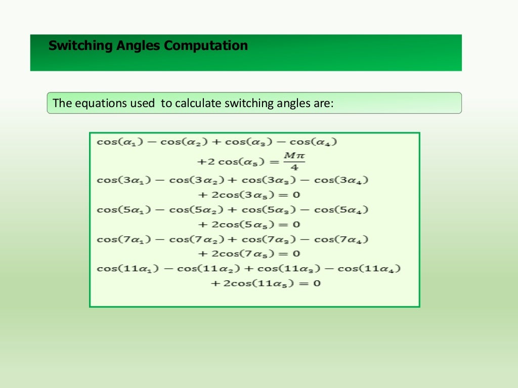
Switching Angles Computation

The equations used to calculate switching angles are:
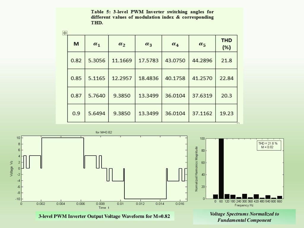
3-level PWM Inverter Output Voltage Waveform for M=0.82

Voltage Spectrums Normalized to
Fundamental Component
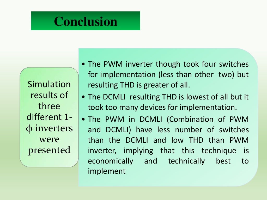
Conclusion
• The PWM inverter though took four switches
for implementation (less than other two) but
Simulation
resulting ...
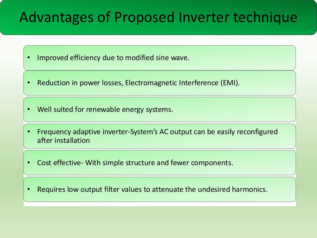
Advantages of Proposed Inverter technique
• Improved efficiency due to modified sine wave.

• Reduction in power losses, E...
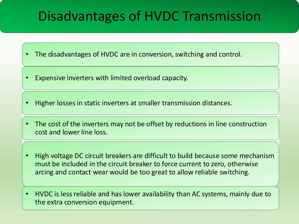
Disadvantages of HVDC Transmission
• The disadvantages of HVDC are in conversion, switching and control.

• Expensive inve...
Control of HVDC Systems

Content

•
•

Efficient and stable operation.
Maximum flexibility of power
control without compro...

Posted on March 31, 2018Categories Electrical & Electronics EngineeringLeave a comment on Dc as a means of transmission

Posts pagination

Page 1 Page 2 Next page
Blog at WordPress.com.
Electrical & Electronics Engineering
Create a free website or blog at WordPress.com.
Privacy & Cookies: This site uses cookies. By continuing to use this website, you agree to their use.
To find out more, including how to control cookies, see here: Cookie Policy
  • Subscribe Subscribed
    Electrical & Electronics Engineering

    Have a WordPress.com account? Log in now.

  • Electrical & Electronics Engineering
    View site in Reader
    Manage subscriptionsSign upLog in
    Report this content
    Collapse this bar
Loading Comments...

You must be logged in to post a comment.

Create your own website, free on WordPress.com.Create your own website.
Start free